Wire-free Miniscope v4: Difference between revisions
No edit summary |
(Zscan feature info added) |
||
| (4 intermediate revisions by 2 users not shown) | |||
| Line 11: | Line 11: | ||
* Recording Length: 20+ minutes with a 45 mAH lipo battery | * Recording Length: 20+ minutes with a 45 mAH lipo battery | ||
* Record Triggering: IR remote control | * Record Triggering: IR remote control | ||
[[File:Dimensions.png|thumb]] | |||
== Overview of System == | == Overview of System == | ||
| Line 18: | Line 19: | ||
=== Setting the conda environment === | === Setting the conda environment === | ||
First, we need to set a conda environment with the Python packages needed for this project, which include: opencv, matplotlib and numpy. If you don't have Anaconda installed on your computer, you can download the installer from [https://www.anaconda.com/ the official Anaconda website]. You can manually install the packages using pip or using the included ''requirements.txt'' file. To do so, clone the Wire-Free repository and open an Anaconda Prompt terminal in the folder ''Miniscope-v4-Wire-Free- | First, we need to set a conda environment with the Python packages needed for this project, which include: opencv, matplotlib and numpy. If you don't have Anaconda installed on your computer, you can download the installer from [https://www.anaconda.com/ the official Anaconda website]. You can manually install the packages using pip or using the included ''requirements.txt'' file. To do so, clone the Wire-Free repository and open an Anaconda Prompt terminal in the folder ''"Miniscope-v4-Wire-Free-Python DAQ Interface".'' | ||
Type the following code into your Anaconda Prompt window: <syntaxhighlight lang="console"> | Type the following code into your Anaconda Prompt window: <syntaxhighlight lang="console"> | ||
conda create --name YOUR_ENV_NAME --file requirements.txt | conda create --name YOUR_ENV_NAME --channel conda-forge --file requirements.txt | ||
</syntaxhighlight>Replace "YOUR_ENV_NAME" with the name you choose for your environment. In the example shown below, I will choose the name '''WFUtils.''' Hit enter to run the line and wait until it finishes solving the environment. | </syntaxhighlight>Replace "YOUR_ENV_NAME" with the name you choose for your environment. In the example shown below, I will choose the name '''WFUtils.''' Hit enter to run the line and wait until it finishes solving the environment. | ||
[[File:Wfutils create env.png|center|thumb|600x600px|Anaconda prompt to create a conda environment using the ''requirements.txt'' file and with a WFUtils name.]] | [[File:Wfutils create env.png|center|thumb|600x600px|Anaconda prompt to create a conda environment using the ''requirements.txt'' file and with a WFUtils name.]] | ||
| Line 201: | Line 202: | ||
[[File:Before and after data saved.png|center|thumb|800x800px|Data sector before (left) and after (right) data has been saved.]] | [[File:Before and after data saved.png|center|thumb|800x800px|Data sector before (left) and after (right) data has been saved.]] | ||
Back in the Jupyter notebook, it is very important to check the PhysicalDrive number before running the script. As we did before, you can run the command ''Get-PhysicalDisk'' in Windows Powershell to retrieve the correct physical drive number.<syntaxhighlight lang="python3"> | |||
Back in the Jupyter notebook, it is very important to check the PhysicalDrive number before running the script. As we did before, you can run the command ''Get-PhysicalDisk'' in Windows Powershell to retrieve the correct physical drive number. | |||
driveName = r"\\.\PhysicalDriveN" # Change this to the correct drive | driveName = r"\\.\PhysicalDriveN" # Change this to the correct drive | ||
</syntaxhighlight>Before running all the cells, it is a good idea to check the file name. If there is an existing file with the same name in the folder where the script is being executed, the new file will overwrite the previous one without any warning. Also, you can change the codec; however, we recommend using GREY as it doesn't have any compression.<syntaxhighlight lang="python3"> | </syntaxhighlight>Before running all the cells, it is a good idea to check the file name. If there is an existing file with the same name in the folder where the script is being executed, the new file will overwrite the previous one without any warning. To avoid this, the script takes a name (in this case ''example'') and adds the current date and time at the moment of running the notebook.<syntaxhighlight lang="python3"> | ||
driveName = r"\\.\PhysicalDrive2" # Change this to the correct drive | |||
videoFileName = "example" + time.strftime("%Y%m%d-%H%M%S") # Video name will be [videoFileName][timestamp].avi | |||
</syntaxhighlight>Also, you can change the codec; however, we recommend using GREY as it doesn't have any compression.<syntaxhighlight lang="python3"> | |||
if saveVideo is True: | if saveVideo is True: | ||
out = cv2.VideoWriter(' | out = cv2.VideoWriter(videoFileName + '.avi', cv2.VideoWriter_fourcc(*'GREY'), | ||
10.0, (configSectorData[CONFIG_BLOCK_WIDTH_POS], configSectorData[CONFIG_BLOCK_HEIGHT_POS] ), | 10.0, (configSectorData[CONFIG_BLOCK_WIDTH_POS], configSectorData[CONFIG_BLOCK_HEIGHT_POS] ), | ||
isColor=False) | isColor=False) | ||
| Line 212: | Line 215: | ||
[[File:Run all cells.png|center|thumb|800x800px]] | [[File:Run all cells.png|center|thumb|800x800px]] | ||
== Z-scan feature == | |||
The v4 Wire-free Miniscope includes a Z-scan feature that sweeps the electrotunable lens across different values to help the user find the best imaging plane for their already baseplated mouse. To use this feature, we first need to set the scan mode flag to true on the ''Set recording parameters - WireFree V4 Miniscope'' notebook<syntaxhighlight lang="python3"> | |||
#v4 Miniscope mode | |||
MINISCOPE_SCAN_MODE = True | |||
</syntaxhighlight>The scan has four variables, which define how the scan is done<syntaxhighlight lang="python3"> | |||
#Settings for scan mode | |||
ewlStart = 10 | |||
ewlStop = 250 | |||
ewlStep = 5 | |||
ewlStepTime = 2 | |||
</syntaxhighlight>The '''ewlStart''' and '''ewlStop''' are the first and last plane, respectively. The minimum value for the first plane is 0, and the maximum for the last plane is 255. The '''ewlStep''' defines the granularity, and the '''ewlStepTime''' how much time it will record at each plane. In the settings above, the recording will record 2 seconds on each plane on a span from 10 to 250, with a granularity of 5 planes. Once the settings are chosen, run the notebook as usual to write the settings on the microSD card and follow the steps to start recording. | |||
To show how the Z-scan recording works, we are going to perform a short recording of a resolution slide and we are going to explain the steps to choose the best imaging plane. Once the recording is done, the data gets extracted the same way as explained in the previous section. | |||
[[File:V4 Wire-free resolution slide.gif|center|304x304px|thumb|v4 Wire-Free performing a Z-scan of a resolution slide (compressed and sped up three times for demonstration purposes).]]Recalling the previous section, once the video has been decoded a CSV file gets generated with the header information. The last column holds the plane value for each frame: | |||
[[File:V4WF header scan.png|center|frameless|700x700px]] | |||
To match the frame number to the EWL value we can use [https://fiji.sc/ FIJI]. Once FIJI is open, load the video. It's very important to load all the frames, like shown in the screenshot below | |||
[[File:V4 WF FIJI.png|center|thumb|FIJI dialog for opening a video.]] | |||
Scroll through the video until the image gets focused. On the top left you will find the corresponding frame | |||
[[File:Screenshot 2024-03-21 at 8.41.53 PM.png|center|thumb|FIJI window showing the frame number on the top left]] | |||
Going back to the timestamp CSV file, we go to the frame number 603 and check the last column (EWL) value. | |||
[[File:EWL value.png|center|frameless|600x600px]] | |||
Now that the best EWL value has been chosen, the recording can be done as usual. To do this, set the Z-scan flag to False<syntaxhighlight lang="python3"> | |||
#v4 Miniscope mode | |||
MINISCOPE_SCAN_MODE = False | |||
</syntaxhighlight> | |||
== MCU Firmware Walkthrough == | == MCU Firmware Walkthrough == | ||
Latest revision as of 15:52, 21 March 2024
The wire-free Miniscope v4 is a battery powered, data logging Miniscope based around the original wired Miniscope v4 project. All code, CAD, and PCB files can be found at https://github.com/Aharoni-Lab/Miniscope-v4-Wire-Free
Specifications
- Weight: 4 grams
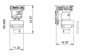
- Size:
- Field of View: 1 mm
- Recording Resolution: 304 (H) x 304 (L) pixels
- Recording Length: 20+ minutes with a 45 mAH lipo battery
- Record Triggering: IR remote control
Overview of System
Workflow of Recording
Setting the conda environment
First, we need to set a conda environment with the Python packages needed for this project, which include: opencv, matplotlib and numpy. If you don't have Anaconda installed on your computer, you can download the installer from the official Anaconda website. You can manually install the packages using pip or using the included requirements.txt file. To do so, clone the Wire-Free repository and open an Anaconda Prompt terminal in the folder "Miniscope-v4-Wire-Free-Python DAQ Interface".
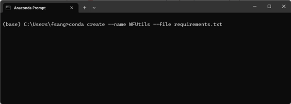
Type the following code into your Anaconda Prompt window:
conda create --name YOUR_ENV_NAME --channel conda-forge --file requirements.txt
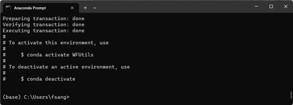
Replace "YOUR_ENV_NAME" with the name you choose for your environment. In the example shown below, I will choose the name WFUtils. Hit enter to run the line and wait until it finishes solving the environment.
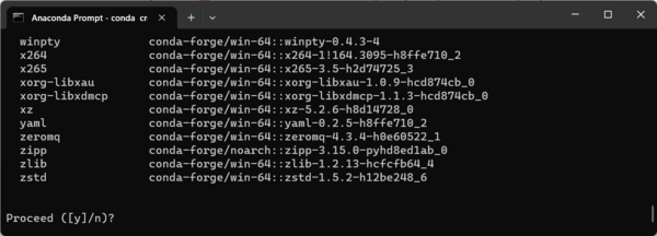
Once the code finishes running, the window will show the following "Proceed" question. Press Y to confirm.
If the installation was successful, the following dialog will appear:
The code shown in the image above is needed to activate the environment. Once successful installation has been confirmed, you may close Anaconda Prompt.
Installing HxD
HxD is a software that can be used to check the contents of any physical drive connected to a computer. It can be used here to check the contents of the SD card that will store the configuration parameters and imaging data. You can download this software here.
Setting the recording parameters in the SD Card
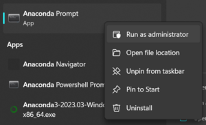
First, run Anaconda Prompt in administrator mode:
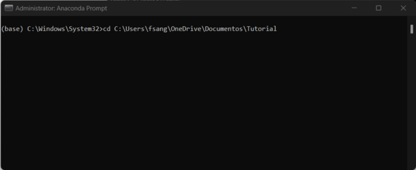
To access your path, change the directory in Anaconda Prompt by using the cd command below. Replace "YOUR_PATH" with the path to your desired folder:
cd YOUR_PATH
Now we have to activate the conda environment that we created. To do so, run the following line
conda activate YOUR_ENV_NAME
Once the conda environment has been activated your environment will change from base to the name of the environment you chose, which in this example case is WFUtils:
Once the path to your folder has been selected and the environment activated, run the following code to open Jupyter:
jupyter notebook
In Jupyter Notebook, open "Set recording parameters." Before running anything, let's check the physical drive number for the SD card. We can do this running Get-PhysicalDisk on a Windows Powershell.
Before connecting the SD Card, we can see the physical drives connected to the computer (shown below). In my case, I have two SSD drives. The enumeration starts at zero.
Once you plug in the SD card and re-run Get-PhysicalDisk, you will see a new connected drive.
The code in Jupyter Notebook has more detailed comments explaining what each cell is doing. However, certain parameters need to be explained. To start, let's make sure that we are effectively working with the SD card. In the following line, the number N should be changed to the actual number of the physical drive. From the screenshot above, we can see that the SD card is physical drive 2.
driveName = r"\\.\PhysicalDriveN"
Then, we run the following cell to erase all the previous data saved in the SD card. Make sure that your data has already been saved in your computer before running this cells. After running this cell, all data is permanently erased.
# Code to erase any previously saved data (if any) in the data sector of the microSD card

f.seek(headerSector * sectorSize, 0)
zeros = np.zeros(sectorSize, dtype=np.uint8)
binaryZeros = bytearray(zeros)
N = 1000000
for i in range(N):
    f.write(binaryZeros)
Now we set the parameters in the header sector. It's important to remember where the data sectors are:
# SD Card sector information
headerSector =          1022 # Holds user settings to configure Miniscope and recording
configSector =          1023 # Holds final settings of the actual recording
dataStartSector =       1024 # Recording data starts here
sectorSize =            512

WRITE_KEY0 =				0x0D7CBA17
WRITE_KEY1 =				0x0D7CBA17
WRITE_KEY2 =				0x0D7CBA17
WRITE_KEY3 =				0x0D7CBA17

# SD Card Header Sector positions
HEADER_GAIN_POS =				4
HEADER_LED_POS =				5
HEADER_EWL_POS =				6
HEADER_RECORD_LENGTH_POS =  	7
HEADER_FRAME_RATE = 			8
HEADER_DELAY_START_POS =		9
HEADER_BATT_CUTOFF_POS =		10
Here, we set our values for the Miniscope. As an example, we will set the gain of the image sensor at 1, the LED at 2, the electrowetting lens at 150, and the frame rate at 20 FPS. We will record for 15 seconds with a 10 second delay after triggering the recording with the infrared remote. If the voltage drops to less than 3300 mV (3.3V), the recording will stop automatically even if it didn't record for the time set before.
# Set the Miniscope parameters
# We have to multiply the index by 4 so they can be 32 bit long (4*byte = 32 bits)

gain = 1                        # Gain 1= 1, Gain 2= 2, Gain 3= 4
led = 2                         # 0 to 100 (0 = LED off)
ewl_pos = 150                   # EWL range= 1 to 255 (0 = EWL off)
recording_length = 15         # Recording length (in seconds)
frame_rate = 20                 # In FPS
battery_cutoff = 3300           # Battery level (millivolts)
delay_start = 10                # In seconds
Once the values are verified, run all the cells. We can check that the parameters have been saved in two different ways. Within the notebook, running the following cell will output the saved parameters:
f.seek(headerSector * sectorSize, 0)  # Move to correct sector
headerSectorData = np.frombuffer(f.read(sectorSize), dtype=np.uint8)
headerSectorData
For the settings above, we get the following output. For parameters that have a value less than 255 we can read them directly from their memory position. For values bigger than 255 we need two bytes for representing the number, and it will be saved in a Little endian representation. For example, the setting of the LED with value 2 can be found in the at the position (4*HEADER_LED_POS)+1 = 21 (please note that we add one due to starting the index numeration at 1 and not 0. If you prefer counting starting at zero just do the multiplication). The position in the header can be found at the beginning of the notebook.
array([  0,   0,   0,   0,   0,   0,   0,   0,   0,   0,   0,   0,   0,
         0,   0,   0,   1,   0,   0,   0,   2,   0,   0,   0, 150,   0,
         0,   0,  15,   0,   0,   0,  20,   0,   0,   0,  10,   0,   0,
         0, 228,  12,   0,   0,   0,   0,   0,   0,   0,   0,   0,   0,
         0,   0,   0,   0,   0,   0,   0,   0,   0,   0,   0,   0,   0,
         0,   0,   0,   0,   0,   0,   0,   0,   0,   0,   0,   0,   0,
         0,   0,   0,   0,   0,   0,   0,   0,   0,   0,   0,   0,   0,
         0,   0,   0,   0,   0,   0,   0,   0,   0,   0,   0,   0,   0,
         0,   0,   0,   0,   0,   0,   0,   0,   0,   0,   0,   0,   0,
         0,   0,   0,   0,   0,   0,   0,   0,   0,   0,   0,   0,   0,
         0,   0,   0,   0,   0,   0,   0,   0,   0,   0,   0,   0,   0,
         0,   0,   0,   0,   0,   0,   0,   0,   0,   0,   0,   0,   0,
         0,   0,   0,   0,   0,   0,   0,   0,   0,   0,   0,   0,   0,
         0,   0,   0,   0,   0,   0,   0,   0,   0,   0,   0,   0,   0,
         0,   0,   0,   0,   0,   0,   0,   0,   0,   0,   0,   0,   0,
         0,   0,   0,   0,   0,   0,   0,   0,   0,   0,   0,   0,   0,
         0,   0,   0,   0,   0,   0,   0,   0,   0,   0,   0,   0,   0,
         0,   0,   0,   0,   0,   0,   0,   0,   0,   0,   0,   0,   0,
         0,   0,   0,   0,   0,   0,   0,   0,   0,   0,   0,   0,   0,
         0,   0,   0,   0,   0,   0,   0,   0,   0,   0,   0,   0,   0,
         0,   0,   0,   0,   0,   0,   0,   0,   0,   0,   0,   0,   0,
         0,   0,   0,   0,   0,   0,   0,   0,   0,   0,   0,   0,   0,
         0,   0,   0,   0,   0,   0,   0,   0,   0,   0,   0,   0,   0,
         0,   0,   0,   0,   0,   0,   0,   0,   0,   0,   0,   0,   0,
         0,   0,   0,   0,   0,   0,   0,   0,   0,   0,   0,   0,   0,
         0,   0,   0,   0,   0,   0,   0,   0,   0,   0,   0,   0,   0,
         0,   0,   0,   0,   0,   0,   0,   0,   0,   0,   0,   0,   0,
         0,   0,   0,   0,   0,   0,   0,   0,   0,   0,   0,   0,   0,
         0,   0,   0,   0,   0,   0,   0,   0,   0,   0,   0,   0,   0,
         0,   0,   0,   0,   0,   0,   0,   0,   0,   0,   0,   0,   0,
         0,   0,   0,   0,   0,   0,   0,   0,   0,   0,   0,   0,   0,
         0,   0,   0,   0,   0,   0,   0,   0,   0,   0,   0,   0,   0,
         0,   0,   0,   0,   0,   0,   0,   0,   0,   0,   0,   0,   0,
         0,   0,   0,   0,   0,   0,   0,   0,   0,   0,   0,   0,   0,
         0,   0,   0,   0,   0,   0,   0,   0,   0,   0,   0,   0,   0,
         0,   0,   0,   0,   0,   0,   0,   0,   0,   0,   0,   0,   0,
         0,   0,   0,   0,   0,   0,   0,   0,   0,   0,   0,   0,   0,
         0,   0,   0,   0,   0,   0,   0,   0,   0,   0,   0,   0,   0,
         0,   0,   0,   0,   0,   0,   0,   0,   0,   0,   0,   0,   0,
         0,   0,   0,   0,   0], dtype=uint8)
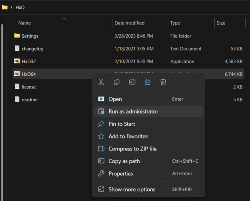
You can also verify this using HxD. In order to check the contents of the SD Card, we need to open it in admin mode. The installer will give two options: 32 or 64 bits. If you are unsure, choose HxD64 as it's highly likely that your computer architecture is 64 bits.
To open the disk, go here:
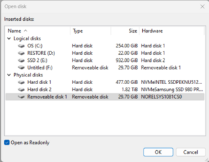
The following dialog will pop up. It's very important to open the disks on the Physical disks list, and that you choose the SD card. In case of doubt check the output of Get-PhysicalDisk:
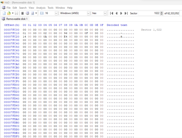
To check your physical disk ID, you have two options. First is to sort by disk size. The Wire-Free ships with a 32 GB SD card, so choose the drive with size similar to that. The other option is to check the hardware name that we got on GetPhysicalDisk before. In this case, the name is NORELSYS 1081CS0. To check the content, we first need to go to Sector 1022, where the header data is. The sector locations can be found at the beginning of the notebook.
To check the contents, we go to the header sector (1022). Here we can see the same output as in the notebook but in hexadecimal representation:
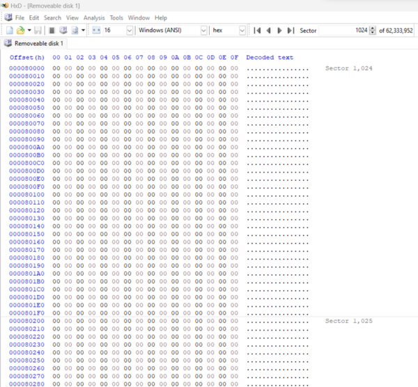
It is also a good idea to check the contents of the sector in which the data is going to be saved, which is Sector 1024. Although it is expected to be zero, it is always a good idea to check that this sector and the following sectors are empty.
Once you have ensured that the parameters are correct, safely eject the SD card as shown below.
How to record using the Wire-Free Miniscope v4
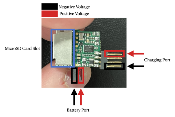
First, we need to understand the electrical connection ports on the PCB. The below diagram is a top view of the Wire-Free Miniscope v4 without the SD card attached (normally fitted into the slot outlined in blue below). It is very important to note the polarity of each electrical port on the Miniscope: reversing the positive and negative connections will damage your Miniscope.
You will connect your battery to the Miniscope via the connector such that the red (positive) wire of the battery attaches to the battery port at the side painted in red (shown below). The charging cable will attach at the charging point with the four-pin connector such that the positive (red) side connects at the positive end labeled blow.
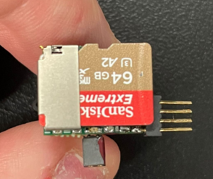
Assuming that the Miniscope parameters have been set and checked, we now insert the SD card in the socket. Make sure that the card is inserted all the way in.
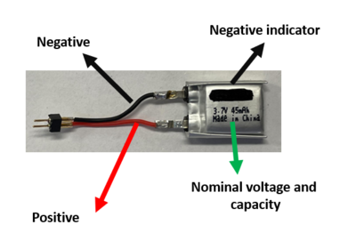
Now we need to connect the battery. To avoid any confusion about the polarity of the battery, we color coded the cables and put a minus (-) mark on the battery to denote the negative.
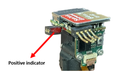
To make sure that the battery is connected in the right orientation, the Miniscope has one side of the connector painted in red to indicate a positive voltage:
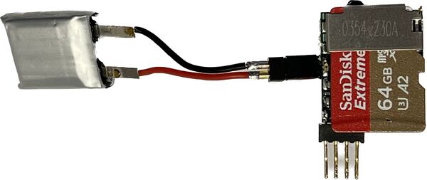
The Miniscope with the battery connected should look like this:
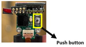
Although the Miniscope is getting powered, it's still not ready to start recording. To turn on the Miniscope, press the button located in the front of the Miniscope for a few seconds:
When the Miniscope is powered on and ready to get triggered for starting the recording, a green LED will turn on.
Now the Miniscope is ready to get triggered and start recording. To start recording, press the button 1 on the remote control. TODO: ADD VIDEO SHOWING THE DELAY BLINK
Extracting Data from SD Card
Once the recording is finished, the imaging data is saved as binary data in the SD card that needs to be reconstructed as a video. We can do this using the notebook "Load raw data from SD card and write video - WireFree V4 Miniscope" in Jupyter that takes the binary data, rearranges it, and encodes it as a video file. In order to read data from the SD card, we need to use the same administrative privileges as we did when we initially set the parameters. Check the above section "Setting the recording parameters in the SD Card" to see a detailed explanation on how to open Jupyter notebook in administrator mode.
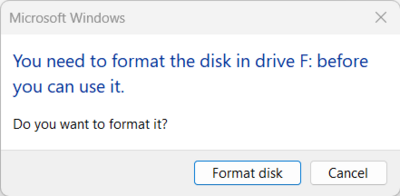
The first step is to connect the SD card into the computer. In Windows you will get the follow dialog:
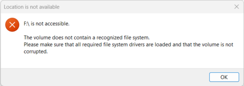
Do not format the disk and click cancel, otherwise it will erase all of your data. Next, you will get the following warning:
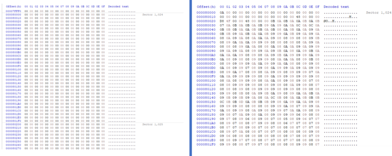
Click OK to exit the dialog. As a sanity check, you can first check the contents of the SD card using HxD. First, we need to open HxD in administrator mode and open the disk as we did in the "Set parameter section." If we go to sector 1024, we can find the data that has been saved. When we initially formatted the SD card before recording, the data sector was cleared and filled with zeroes to indicate it is empty and ready to store data (shown below on the left). After recording, we can see that the same 1024 sector has now been filled with imaging data represented in hexadecimal format (shown below on the right).
Back in the Jupyter notebook, it is very important to check the PhysicalDrive number before running the script. As we did before, you can run the command Get-PhysicalDisk in Windows Powershell to retrieve the correct physical drive number.
driveName = r"\\.\PhysicalDriveN" # Change this to the correct drive
Before running all the cells, it is a good idea to check the file name. If there is an existing file with the same name in the folder where the script is being executed, the new file will overwrite the previous one without any warning. To avoid this, the script takes a name (in this case example) and adds the current date and time at the moment of running the notebook.
driveName = r"\\.\PhysicalDrive2"  # Change this to the correct drive
videoFileName = "example" + time.strftime("%Y%m%d-%H%M%S") # Video name will be [videoFileName][timestamp].avi
Also, you can change the codec; however, we recommend using GREY as it doesn't have any compression.
if saveVideo is True:
    out = cv2.VideoWriter(videoFileName + '.avi', cv2.VideoWriter_fourcc(*'GREY'),
                        10.0, (configSectorData[CONFIG_BLOCK_WIDTH_POS], configSectorData[CONFIG_BLOCK_HEIGHT_POS] ),
                        isColor=False)
Once the drive number and file name has been set, we can run all the cells to convert the data to a video file:
Z-scan feature
The v4 Wire-free Miniscope includes a Z-scan feature that sweeps the electrotunable lens across different values to help the user find the best imaging plane for their already baseplated mouse. To use this feature, we first need to set the scan mode flag to true on the Set recording parameters - WireFree V4 Miniscope notebook
#v4 Miniscope mode

MINISCOPE_SCAN_MODE = True
The scan has four variables, which define how the scan is done
#Settings for scan mode

ewlStart = 10
ewlStop = 250
ewlStep = 5
ewlStepTime = 2
The ewlStart and ewlStop are the first and last plane, respectively. The minimum value for the first plane is 0, and the maximum for the last plane is 255. The ewlStep defines the granularity, and the ewlStepTime how much time it will record at each plane. In the settings above, the recording will record 2 seconds on each plane on a span from 10 to 250, with a granularity of 5 planes. Once the settings are chosen, run the notebook as usual to write the settings on the microSD card and follow the steps to start recording.
To show how the Z-scan recording works, we are going to perform a short recording of a resolution slide and we are going to explain the steps to choose the best imaging plane. Once the recording is done, the data gets extracted the same way as explained in the previous section.
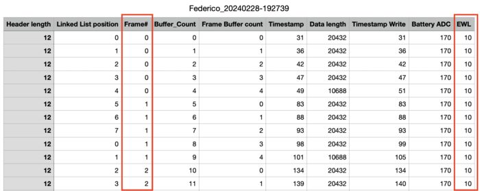
Recalling the previous section, once the video has been decoded a CSV file gets generated with the header information. The last column holds the plane value for each frame:
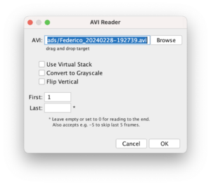
To match the frame number to the EWL value we can use FIJI. Once FIJI is open, load the video. It's very important to load all the frames, like shown in the screenshot below
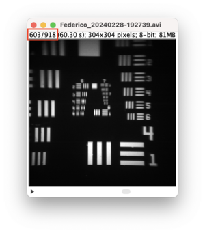
Scroll through the video until the image gets focused. On the top left you will find the corresponding frame
Going back to the timestamp CSV file, we go to the frame number 603 and check the last column (EWL) value.
Now that the best EWL value has been chosen, the recording can be done as usual. To do this, set the Z-scan flag to False
#v4 Miniscope mode

MINISCOPE_SCAN_MODE = False
MCU Firmware Walkthrough
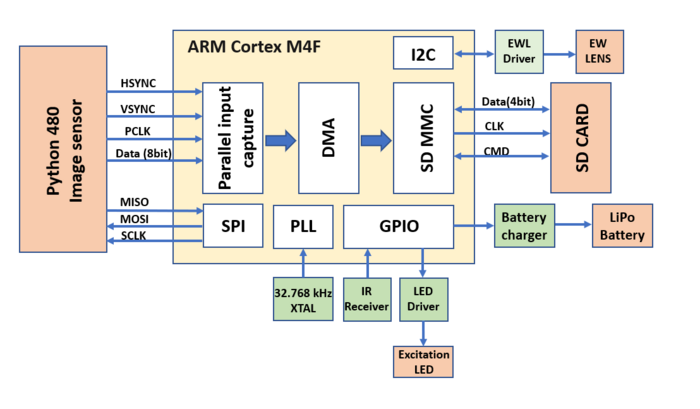
The microcontroller (MCU) used in the Wire-Free Miniscope v4 is an ATSAMD51. It sits between the Python 480 CMOS image sensor and the micro SD Card and handles all on-board control and operation of the Miniscope. The firmware uses a combination of custom written driver and ones imported using ATMEL SMART.
Initialization
- atmel_start_init()
- This function calls init_mcu() which sets up clocks, configs and enable DMA, and enables/disables cache.
- This function also sets up the initial configurations mainly defined by the ATMEL SMART interface. This includes setting GPIO direction and mode and initalizing the ADC, external interrupts, PPC, USART, PWM, SYSTick, and Timers.
- This function also does some minor stuff to initalize the sd_mmc stack.
- Next we do some additional manual configuration of the PWM mode, enabling the 3.3V external regulator, and enabling the ADC.
- Due to pin limitations when using both the PCC module and SD Card module, we don't have access to directly using the SERCOM I2C functionality of this particular MCU. This means we need to implement I2C ourselves using a "Big Back" approach. We set this all up in I2C_BB_init() and all of the I2C Big Bang functionality is done in i2c_bb.c.
- Next we setup timers that let us keep track of the time in milliseconds, TIMER_0_taks1, and check the Lipo battery voltage every once-in-a-while, TIMER_0_task2.
- Next we construct our DMA/Buffer linked lists in linkedListInit(). More information on this can be found below.
- Next we wait until we detect an SD Card in mounted on the PCB, read the header memory block (block 1022) using loadSDCardHeader(), and configure the SDHC module to run using ADMA.
- Next we setup the Python 480 by toggling its reset pin, sending it initial register values using python480Init(), and then configuring its registers for subsampling, gain, FPS, etc.
- Finally, we write some initial configuration information into SD card memory block 1023 and then set deviceState = DEVICE_STATE_START_RECORDING to trigger the event to begin recording imaging data.
Buffers
The MCU firmware creates a circular buffer to fill and hold pixel data. This set of buffers should each have a size a multiple of 512 bytes so that each can be nicely written into an SD Card whose memory blocks are 512 bytes in size. Outside of the constraint that each buffer should be some multiple of 512 bytes there are no other constraints in terms of number of buffers or buffer size relative to image sensor frame size.
The circular buffers are defined globally within main.c :
COMPILER_ALIGNED(4)
volatile uint32_t dataBuffer[NUM_BUFFERS][BUFFER_BLOCK_LENGTH * BLOCK_SIZE_IN_WORDS]; //Allocate memory for DMA image buffers
This set of buffers gets circularly iterated through using DMA linked lists as pixel data arrives from the image sensor. Once a buffer is full, or once the end of a frame arrives and we have a partially filled buffer, the buffer becomes available to be written to the SD Card using ADMA.
State Machine
// ---------- Device State Definitions -------
#define DEVICE_STATE_IDLE				1<<1
#define DEVICE_STATE_START_RECORDING	1<<2
#define DEVICE_STATE_RECORDING			1<<3
#define DEVICE_STATE_STOP_RECORDING		1<<4
#define DEVICE_STATE_CHARGING			1<<5
#define DEVICE_STATE_CONFIG_LOADED		1<<6
#define DEVICE_STATE_ERROR				1<<7
#define DEVICE_STATE_LOW_VOLTAGE		1<<8
#define DEVICE_STATE_START_RECORDING_WAITING	1<<9
#define DEVICE_STATE_SDCARD_WRITE_ERROR			1<<10
#define DEVICE_STATE_SDCARD_INIT_WRITE_ERROR	1<<11
- The device state initially starts off in DEVICE_STATE_IDLE.
- To begin recording, the device start needs to be set to DEVICE_STATE_START_RECORDING. This lets the MCU know that we need to prepare everything to start a new recording session.
- Once the MCU prepares itself, it moves its device state to DEVICE_STATE_START_RECORDING_WAITING. This state is managed within the frameValid_cb function and makes the MCU wait until the end of the last frame is received before enabling the PCC DMA so that data buffers can start being filled and counted when the start of the next frame begins to arrive. Once the MCU enables the PCC DMA, it will move the device state to DEVICE_STATE_RECORDING.
- Once the MCU moves into the device = DEVICE_STATE_RECORDING, management of detecting newly filled buffers and sending those over to the SD Card is all handed within the function void recording(). recording() is continuously called within the while loop in main().
Callback Functions
Callback functions handle specific events within the MCU that generate interrupts. Roughly speaking, when certain interrupts happen, the MCU will jump from wherever it is currently in its code, to the callback function linked to this interrupt event. Callback functions are denoted with a '_cb' at the end of their function name:
// callbacks
static void millisecondTimer_cb(const struct timer_task *const timer_task);
static void checkBattVoltage_cb(const struct timer_task *const timer_task);

static void battCharging_cb(void);
static void irReceive_cb(void);
static void pushButton_cb(void);
static void frameValid_cb(void);
Many of these callback functions are connected to a specific external interrupt (basically the input on an MCU pin changing a certain way) which is done near the top of main():
// Setup callbacks for external interrupts
	ext_irq_register(PIN_PB22, irReceive_cb);
	ext_irq_register(PIN_PB23, battCharging_cb);
	ext_irq_register(PIN_PB14, frameValid_cb);
	ext_irq_register(PIN_PA25, pushButton_cb);
The DMA callback function is pcc_dma_cb() and gets linked to the DMA interrupt in main() using camera_async_register_callback.
DMA
The MCU using Direct Memory Access (DMA) to stream pixel data into memory from the image sensor as well as write imaging data from memory into the SD Card. For pixel data coming from the image sensor, the MCU uses its Parallel Capture Controller (PCC) with DMA to handle an 8-bit parallel pixel bus. For writing imaging data into the SD Card, the MCU uses its ADMA to move raw data in the MCU memory into the SD Card storage blocks.
PCC DMA (Image Sensor -> MCU Memory)
Linked List DMA Descriptors
COMPILER_ALIGNED(16) // Taken from hpl_dmac.c but I think this could be '8' since descriptors need to be 64bit aligned from data sheet
volatile DmacDescriptor linkedList[NUM_BUFFERS];
PCC DMA Callback
Once a DMA transfer has completed, the pcc_dma_cb function gets called. This callback function will update the header portion of the last written into buffer using the setBufferHeader function and increment the bufferCount and frameBufferCount.
SD Card ADMA (MCU Memory -> SD Card)
Writing and reading from the SD Card takes advantage of ADMA. I can't quite remember what all the differences are here between ADMA and regular DMA but it took a while to get up and running. To get everything up and running in the firmware, I added two additional functions in sd_mmc.c:
- sd_mmc_err_t sd_mmc_write_with_ADMA(uint8_t slot, uint32_t start, uint32_t *descAdd, uint16_t nb_block)
- sd_mmc_err_t sd_mmc_wait_end_of_ADMA_write(bool abort)
